Dstar Modification/Test
DSTAR Repeater Modifications & Interference Testing
By
NU5D
Overview
Icom produces four different repeater modules and one controller in their
DSTAR product line. One controller can serve any mix of four repeater modules.
The repeaters start out as basic FM radio sets with traditional transmitter and
receiver components and look to be constructed using ID-1 mobile radio
chassis components. Each receiver has a traditional FM detector and provides a
test point for discriminator or wide bandwidth recovered audio. Each transmitter
uses a semi standard press to talk line called TXE and is equipped with a direct
FM varactor diode modulator.
There are several tests commonly performed with analog FM repeaters that are
also useful in testing DSTAR repeaters. The repeater module test points,
however, are not readily accessible as shipped. Therefore a few simple
modifications need to be performed.
Before getting into the modifications let me say a little about the tests. The first
test, Effective Sensitivity, is a measure of how much noise the repeater's
surroundings introduce and impair receiver performance. The second test,
Receiver Desensitization, will measure the degree to which the repeater
transmitter impairs receiver performance.
Some test equipment is needed to measure Effective Sensitivity. You will need a
signal source or generator, an Isolated TEE or cross coupler with at least 50 dB
of isolation, and a 50 Ohm dummy load. The purpose of the Isolated TEE is to
inject a known signal into the receive port without significantly loading any
signal presented by the antenna. (In duplex antenna systems this isolation
allows you to operate the transmitter without damaging the signal generator). A
50 Ohm dummy load is used as a quiet antenna to establish a reference point,
(receiver noise floor).
You need to be able to monitor the received signal either with a loudspeaker or
a tap into the discriminator of the receiver. It is helpful to have a means of
measuring the quality of the received signal such as a SINADDER (Signal to Noise
and Distortion Meter) or a Flat Meter to measure the degree of receiver quieting
when a signal is applied to the receiver antenna port. The industry accepted
standards for a usable received signal is 12 dB SINAD or 20 dB of Receiver
Quieting. I prefer SINAD because it gives a better overall measure of
performance and includes distortion as well as quieting.
A signal with 12 dB SINAD will have some noise but will be intelligible. These
tests and modifications do not address digital signal recovery or regeneration or
bit error rate performance. They do provide a means of identifying and
measuring interference sources and system degradation ahead of the digital
circuitry.
Test Procedure
Connect the SINAD meter to the receive discriminator test port or loudspeaker.
Note: without a signal at the antenna there should be zero dB. of SINAD – all
noise. Connect the receive antenna port to the Isolated TEE and terminate the
TEE into a 50 Ohm load. Connect the signal generator to the isolated tap on the
TEE and set the generator to produce an on frequency signal at a level of around
-60 dBm modulated in FM with a 1000 Hertz tone and the frequency deviation
set to +/- 1.5 kHz deviation (1000 Hz. @ +/- 1.5 kHz is a standard 60% full
system deviation test tone). Fine adjust the generator output to produce a 12 dB
SINAD on the received signal quality meter. Make note of the generator output
level needed for 12 dB SINAD. This number, minus the coupling loss in the
Isolated TEE is the receiver sensitivity for 12 dB. SINAD. This should be around -
115 dBm or so. (The +/- 1.5 kHz. FM deviation setting is consistent with 60%
modulation on 12.5 kHz bandwidth FM receiver systems).
Remove any receiver preamplifiers before testing. Using a preamplifier will make
existing problems more pronounced. Test without preamplifiers first, then if all
is well, add the preamp and re-test.
Next remove the dummy load and connect the station antenna in its place. The
signal from the generator will now have some real world noise to contend with
that should cause more signal from the generator to be needed for the same 12
dB SINAD reading on the signal quality meter. It is not uncommon to see an
impairment of several dB caused by outside noise sources.
If you are using a single antenna and duplexer the Isolated TEE goes on the
Antenna Port of the Duplexer because both local noise and the desired signal
mix before the signal gets to the duplexer. I did encounter an unexpected result
at this point. The signal from the generator into the TEE was well above the
noise, and suddenly the test tone disappeared and a steady burst of noise took
over. This happened several times. I finally figured out by listening to the IC91
that one of the local hams was making a call through the repeater.
Finally you will need to turn the DSTAR Repeater transmitter on and off to see if
additional impairment is caused when the transmitter is active. This calls for the
second repeater modification of the TX radio and allows the second test,
Receiver Desensitization to be performed. The Receiver Desensitization test is
the same as the Effective Sensitivity test except you turn the repeater's
transmitter off and on to see if your own transmitter is causing impairment to
your receiver. Try this first without any external power amplifiers. If there is
receiver desensitization without an external power amplifier, fix that problem
first, then test with the amplifier. Also go back to the dummy load (capable of
absorbing the transmitters rated output) and switch between the dummy load
and antenna. This will let you know whether receiver desensitization is taking
place inside the repeater and duplexer system, or in the transmission line and
antenna system. One system operator recommends using DPLUS with a local
terminal to play a message through the repeater, thereby turning on the
transmitter. I also have used my IC91 with a dummy load (to keep stray RF
down) on 2M to operate the 70CM transmitter. For me the PTT modification was
convenient, but there are certainly other ways to activate the repeater's
transmitter.
There are many online lists with advice and information (some useful) about
resolving interference and noise problems and I will not attempt to go into these
details.
https://www.youtube.com/watch?v=hvouX-K5AFg
Repeater Modifications – NOT APPROVED by ICOM and MAY CAUSE
DAMAGE to your REPEATER. DO THIS AT YOUR OWN RISK! There is no
warranty implied or offered and your mileage may vary.
Modification 1 – Discriminator Tap.ra in
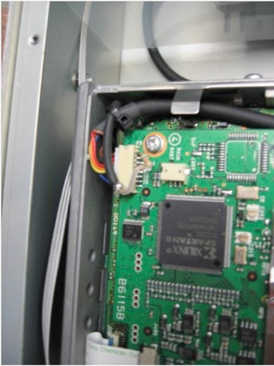
Figure 1
Figure 1 above is the 1.2 GHz RP2V DSTAR Receiver MOD. A 68K Ohm resistor is
attached to the 8th pin of the internal connector and runs through an openi
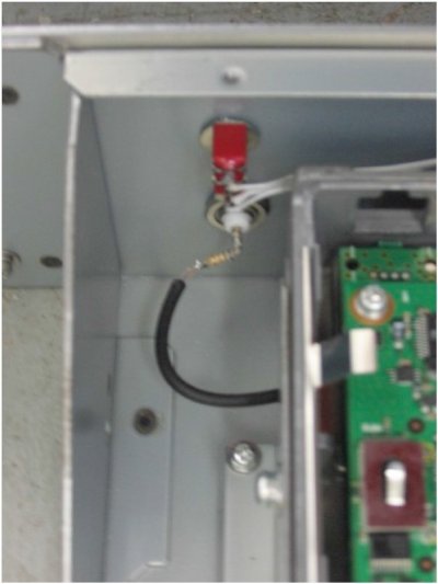
the front of the receiver to a Chassis Mounted BNC connector mounted in the
front panel of the repeater. Figure 2 below is the front panel switch and jack.
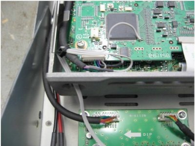
Modification 2 – Front Panel PTT Control
I found some single throw double throw toggle switches with Momentary ON
and Center OFF positions. I mounted this type of switch on the front of each
repeater module. The idea is to provide a NORMAL, OFF, and Momentary PTT
switch position. PTT in a DSTAR Repeater comes from the RP2C repeater
controller. 3.1 VDC from the controller is applied to the TXE lead (a violet lead in
the TX radio as shown in Figure 3 below)
I broke the VIOLET TXE lead from the RP2C controller near the connector on the
TX radio control board. The TXE Lead from the RP2C goes to the NORMAL side
of the toggle switch. +3.24 VDC used to power the controller microprocessor
goes to the Momentary side of the Toggle switch. The Center OFF position on
the switch disconnects the PTT line from both the RP2C controller and the 3.24
VDC source, so the TX Radio cannot transmit. In the NORMAL position the signal
from the RP2C goes through the UP position on the switch and lets the
controller operate the transmitter as needed. The PTT or Momentary DOWN
position on the switch disconnects the control board from the RP2C and
Momentarily connects the TX Radio TXE lead to +3.24 VDC to allow momentary
keying of the transmitter. I first thought about using diodes to isolate a Manual
Key line but I was concerned that the 0.7V drop across the diode junction may
be too much to permit reliable keying. The 3 position switch also allows the technician to disconnect the TX line from the controller and prevent accidental
TX operation during testing. The procedure is very similar on the 2M and 70CM
repeaters except the 3.24 VDC power source that powers the microprocessor is
at a slightly different location.
That is pretty much it in a nutshell. I recommend that only an experienced
technician with reasonable skills attempt this modification with proper ESD
protection, and be sure safety measures such as proper fusing, and so forth are
applied. Again this is at your own risk and I assume NO LIABILITY if you thrash
your repeater. Let the buyer beware.
Steve NU5D